|
This is a little page with lots of pretty pictures and
graphs about my dual inverted V antenna for 40m. I prefer the Inverted V dipole over a horizontal dipole as it has a 50 ohm impedance, uses one light weight support and has almost the same gain as a horizontal dipole. |
|
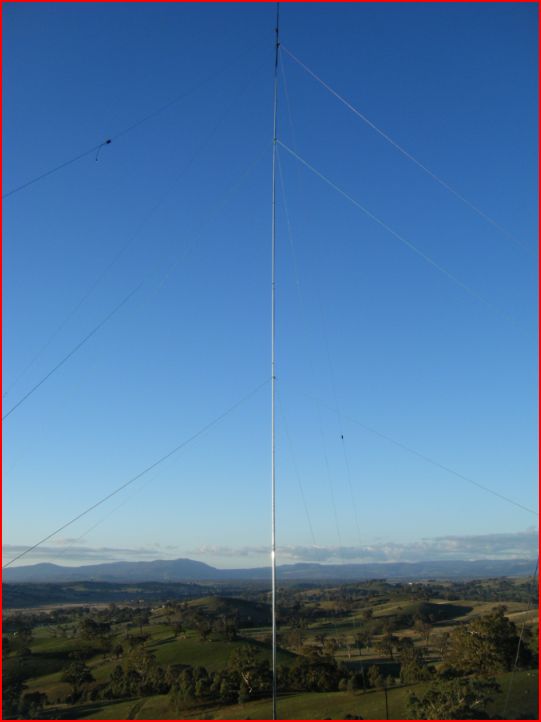
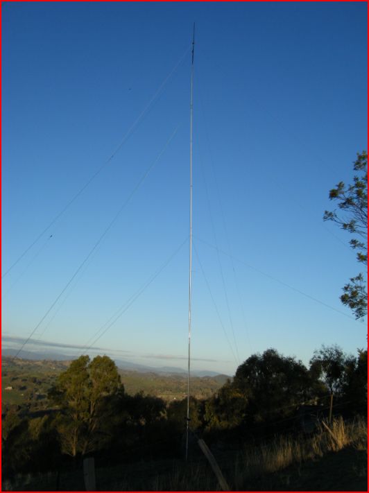
The image above shows my 2 Inverted V dipole antennas
for 40M, 1/2 Wave length high, each with it's own feed and 1:1 balun.
I switch between them as needed from the shack.
|
| At 1/2 a wavelength there is enough directional difference between the 2 antennas to create atleast 1 full S point of change at both ends of the QSO between the 2 antennas in most tests. These results have been repeated in practice on many occasions. At 1/4 wavelength high there is no noticeable difference between the 2 antennas in tests. |
|
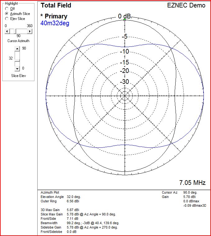
There is almost no interaction when the two antennas are perpendicular and stacked, however they do interact as soon as they are moved out of the perpendicular position. Infact this setup shows the lowest interaction between the two antennas in any configuration short of them being more than 50m apart. Bellow is the plot of 2 Inverted V's for 40m stacked 50cm apart at 20m
in height. Take off angle is 32 deg (maximum gain), however the gain difference
between the nulls and lobes increases further at lower angles up to around
10 db. |
| Compared to a full quarter wave vertical the inverted V dipole at 1/2 a wavelength compares well or better in most cases, especially when you have 2 inverted v dipoles to switch between to prevent significant nuls. Infact there is more gain on the inverted V (at 1/2 a wave high) down to about 8 deg take off and more available if more height is added. With a vertical, you don't really get any gain at all, and increasing height doesn't help, as the ground increases in height aswell. (i.e. if you managed to elevate the radials) |
|
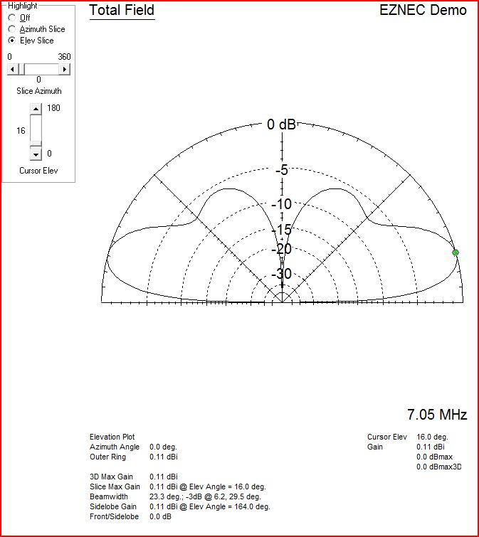
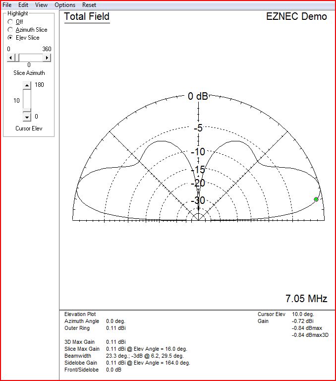
Here is a vertical for 40m with 16 radials. It has .11
dbi gain at 16 deg and lower gain at medium angles.
|
|
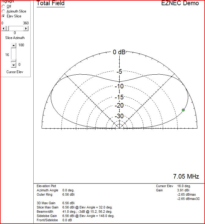
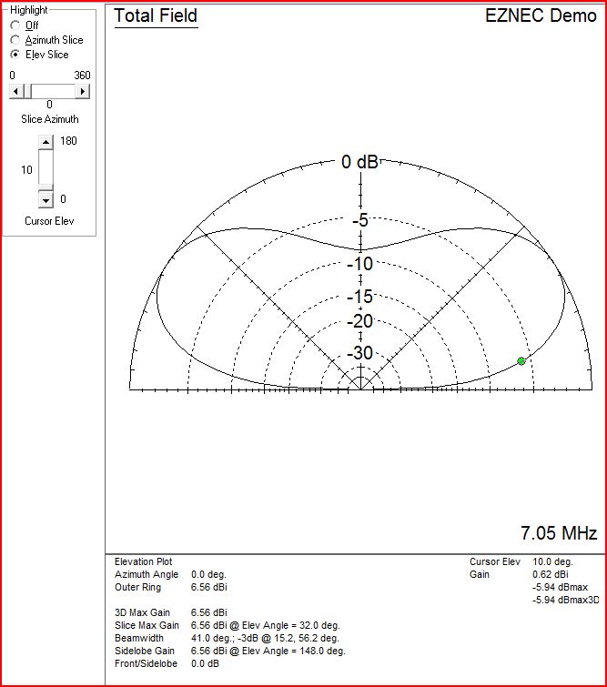
Here is an inverted V at 1/2 wavelength high at 16 Deg
takeoff. It shows 4dbi of Gain, plus the bonus a couple more db at higher,
but still useful, takeoff angles. 4db more than doubles the effective radiated power and 16 deg take off is a good DX take off angle. |
|
Ok, but what about really low take offs ? Most propagation prediction software predicts that take offs around 10 deg - 15 deg work the best for the longest DX circuits The vertical at 10deg shows -0.72 dbi gain |
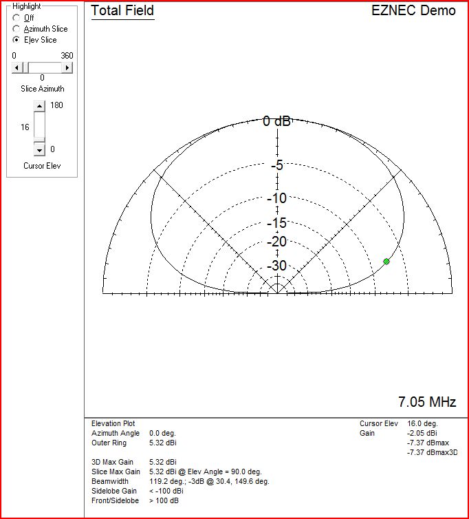
The inverted V dipole at 1/2 a wavelength high still wins here
too with 0.6dbi gain at 10 deg, although move off broadside where the gain goes
drops the Vertical
becomes more equal or even slightly better
|
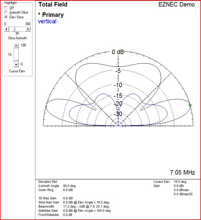
At bellow 10 deg takeoff, the vertical exhibits a slight advantage over the inverted V dipole at 1/2 wavelength high, however you can increase the gain of the inverted V at the lower angles by adding some more height to it. Here is an inverted V at one wavelength high compared to the Vertical Ground plane (at any height). If you live on a hill with decent drop offs then the height the inverted V dipole 'sees' might be higher than support height. I recommend using YTAB for take off angle prediction from hills (for horizontal antennas only). I have done some work modeling my QTH with YTAB and will make a webpage with the graphs when I get a chance. If you can get your dipole up 1 wavelength either through mast height or possibly hill height then you would see the follow radiation pattern. Black being inverted V dipole at 1 wavelength in height and blue being the vertical ground plane.
|
On the other hand if you have your 7mhz V dipole at 10m in height
(ie 1/4 wave length high) then you are radiating 1/4 of the power at 16 deg
compared to 1/2 wave length in height.
That means the guy running 100 watts with his dipole antenna at 1/2 wave high
is putting out over 200 watts effective power at 16 deg, compared to the guy
(or girl !)
with their antenna at 1/4 wave high running 100watts who is radiating around
60 watts at 16 deg and the gap gets larger as the height difference increases.
A vertical is more effecient than a dipole at 1/4 wavelength high at DX takeoffs,
but then dipole wins when it gets higher.
|
Of course the above results are simulated in the direction of highest
gain of the inverted V (i.e. broadside) The inverted V is directional
at height, while the Vertical is omnidirectional, This page is still in progress. |
|
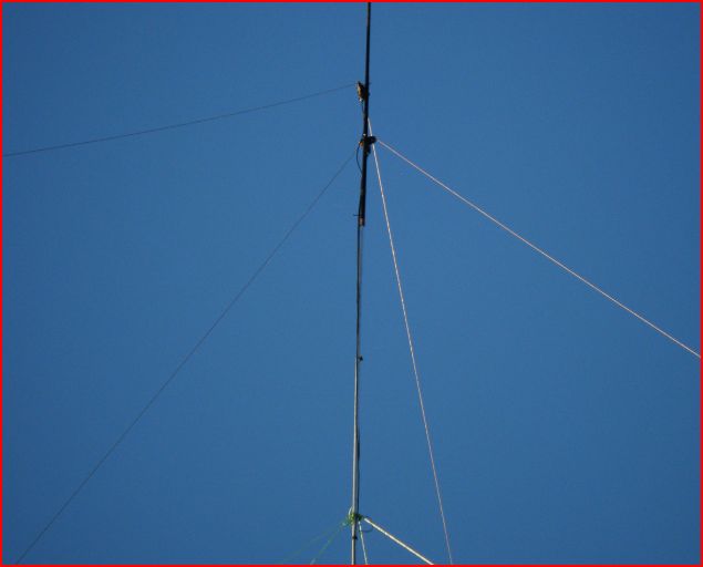
Here are a few extra pictures of the inverted V dipole. This is the top section showing a 1 metre section of fiberglass to which are attached 2 x 1:1 commercial baluns (to ensure radiation pattern isn't distorted from feedline radiation). The telescopic mast is also guyed using plastic coated, non conductive poly rope at 2 points. |
|
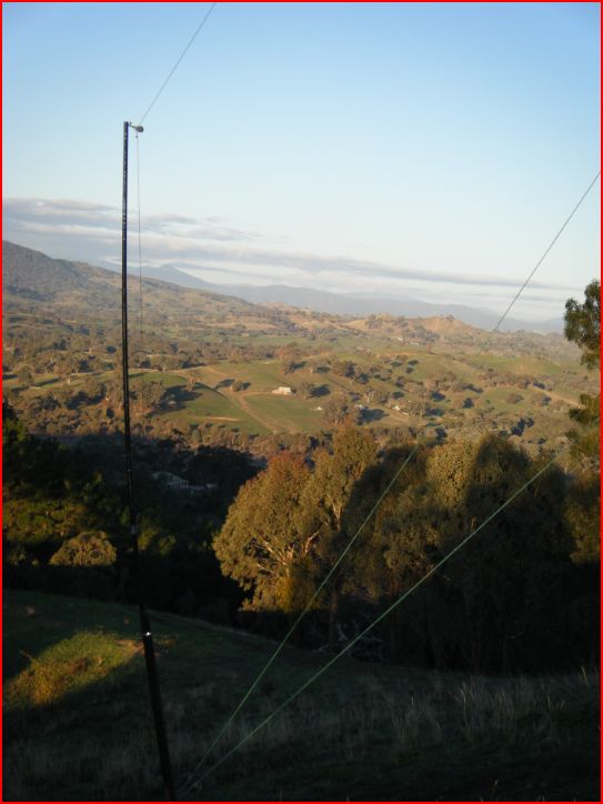
As the top of the mast is high the side of the inverted V need to be raised to stop the apex angle of the V been too small, which results in inefficiencies. This support is 3m of fiberglass with a pully on the top. The inverted V is held in place with kevlar rope. |
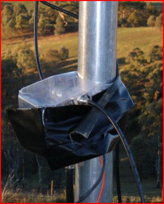
This is the relay / switch that is used to choose between the
2 antennas.
Yes it is very "bodgely" mounted at the moment !
The is the SE View. This is the long path into Europe, which works very well, with daily contact into Europe around 3 - 5pm EST.
Recordings
I will have to get this webpage a bit more organised one day, but for now, I'll list my recordings here. These recording are of contacts made on the 40M DX Netwhich VK6JB and myself run each Wednesday, Friday and Saturday at 12:00 UTC on 7.092.. Click on the links bellow to have a listen.
http://www.mansfieldweather.com.au/vk3lmr/ve6ao-jb0baw.mp3
http://www.mansfieldweather.com.au/vk3lmr/vk4acb-ur2tz.mp3
http://www.mansfieldweather.com.au/vk3lmr/vk6fdx-3d2mp.mp3
http://www.mansfieldweather.com.au/vk3lmr/vk6wc-3d2mp.mp3
http://www.mansfieldweather.com.au/vk3lmr/vk2farr-ve6ao.mp3
http://www.mansfieldweather.com.au/vk3lmr/vk2mjw-ur2tz.mp3